
Universal Tower Accessory Shelf
- Details
- Category: Homebrew
- Published on Wednesday, 17 September 2014 19:44
- Written by David L Norris, KG9AE
At W9CRC, we needed a couple of rotor brackets. One to hold a Yaesu G-5500 azimuth rotor and another for a thrust bearing. In looking online I see that many people have been making homebrew adaptor plates to convert a Hy-Gain/Rohn style shelf to a Yaesu 85mm bolt pattern.
Instead of bolt holes I have cut slots for 6 bolts centered directly on the mast. You can see the geometry and layout in the CAD file. The holes are big enough to fit both Hy-Gain and Yaesu rotors. Since the slots had to extend into the keyhole I suggest (and will include) some large washers to place on both sides of the metal plate just for good measure.
I am working on having a number of these waterjet cut out of 0.1" galvanized steel and to have tabs folded in a break press. Though I will have some available without the bent tabs. The tabs are extra-long to accommodate smaller tower sizes. The full size fits a Rohn 25G or similar.
This CAD file is available in AutoCAD 2013 (dwg), AutoCAD 2013 (dxf) and STL files.
If you have improvements or would like it converted to another CAD format contact me via Google+.

KLM Satellite Antenna Parts
- Details
- Category: Homebrew
- Published on Sunday, 23 March 2014 23:31
- Written by David L Norris, KG9AE
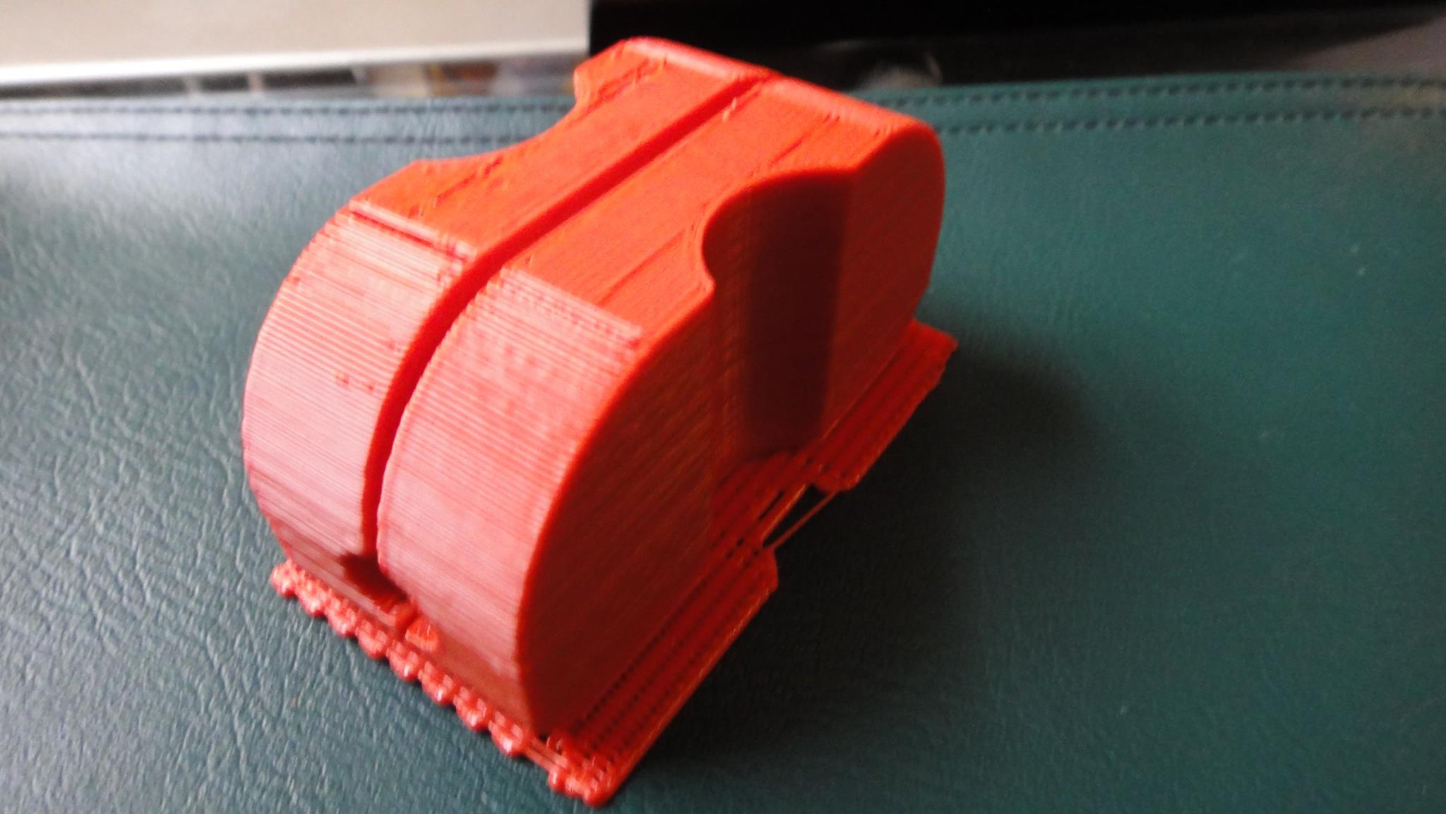
STL and Inventor files for replacement driven element insulators on a KLM 2M-22C, KLM 435-40CX and similar antennas made from the mid 1980s to early 1990s. 3D Print this part in ABS with solid infill then drill holes for the screws where you need them. Mast diameter is 1 inch and driven element diameter is 3/8 inch. The overall dimensions are 3" x 1.5" x 0.625"
Thanks to Doug Keenan for printing out a couple of these for the W9CRC ham radio club!
Troubles with Arduino on the 'Tiny85
- Details
- Category: Shack Talk
- Published on Thursday, 06 September 2012 03:57
- Written by David L Norris, KG9AE
The attiny85 and family are excellent little microcontrollers fit for many simple uses like lamp dimmers and other simple automation tasks. The folks at MIT Media Labs "High-Low Tech" group have put together board definitions for various "tiny" AVR chips including the attiny44, attiny45, attiny84 and attiny85. You can read all about programming and interfacing these chips at their website:
http://hlt.media.mit.edu/?p=1695
What's Going Wrong?
However, many folks including myself have been plagued by a simple problem when attempting to program the attiny85. During upload you get the following error and your red LED error light may illuminate:
avrdude: stk500_paged_write(): (a) protocol error, expect=0x14, resp=0x64
avrdude: stk500_cmd(): protocol error
I have seen a million reasons for this and some people don't seem to want to state the exact cause in various forums. So I hope this article finds those who need to resolve this issue.
Why?
Why does this occur? Quite simply, the Arduino 1.0 IDE sets the baud rate of the ISP sketch to 19,200 bps and the attiny is way slower than that. Two simple modifications will resolve the issue.
-
Open the ArduinoISP Sketch by selecting File -> Examples -> ArduinoISP
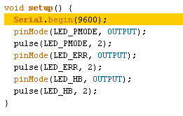 Locate the setup() function in the code and change the Serial.begin() to 9600 from the default 19200 and save the sketch to your custom sketches folder.
- Upload this modified sketch to your Arduino ISP programmer board.
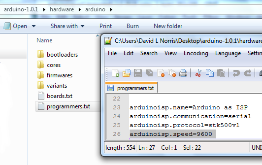
- Edit your programmers.txt file to communicate with "Arduino as ISP" programmers using 9600 baud.
- You may now upload sketches to your attiny microcontrollers! Try the blink sketch as described on the HLT website.
- Enjoy!
Radiometry: Detecting Light Levels
- Details
- Category: Shack Talk
- Published on Wednesday, 05 September 2012 03:26
- Written by David L Norris, KG9AE
The emissivity of a body is equal to its absorbance at the same temperature.
G.R. Kirchhoff, Kirchhoff's Law of Radiation.
This article describes a simple radiometer for the measurement of visible and invisible light.
According to "Meteorology: The Atmosphere and the Science of Weather, Fourth Edition", J Moran & M Morgan (isbn:0023833416), Meteorologists use a scale from 1-10 to describe the sky conditions. 1 being completely clear and 10 being completely overcast. Using a simple integrated analog to digital convertor, it should be possible to directly interface the sensor to a computer serial port.
So, you want to build a radiometer
Well, I made it to chapter two of the Meteorology book before I was distracted. Chapter Two: Radiation, Figure 23: Pyranometer; A Pyranometer is a somewhat crude form of radiometer. More specifically, a Pyranometer is a radiometer which measures the intensity of solar radiation striking a horizontal surface. I call it a crude radiometer because it consists of a disc with six 60 degree wedges alternately painted black (absorb desired wavelength) and white (reflect desired wavelength). Not necessarily a literal/visible black and white color mind you, black and white according to the absorbency and reflectance of the materials at the desired wavelengths of radiant electromagnetic (radio) energy. A radio flux measurement is taken by determining the temperature difference between the two surfaces. Two key ingredients, a consistently transparent hemisphere and a detector with a reasonably high radio flux at the desired wavelengths. The goal is to transmit direct plus diffused light to the radio detector. You want to preserve the variance of intensity from sunlight at high angles (direct) versus sunlight striking the surface from low angles (diffused). The higher the angle of radiation, the more concentrated it becomes. A beam of radio waves with a lower radiation angle is spread over a larger surface area. Thus, for accurate results you need to take measurements over a large surface area.
Goals
- Not too crude
- Output variable voltage
- Ridiculously simple
- Detect infrared, visible, and/or ultraviolet wavelengths
We have two options
- A commercial $200+ radiometer
- An array of $0.39 photo-emissive diodes (LED)
Now that we have chosen LEDs
At minimum, an array of three super bright LEDs per wavelength. I choose three sensors because we want to measure the radio flux over a wide surface area. The typical surface area of a large LED is 211.6 sq millimeters (460 x 460 micrometers). Four sensors would be a waste and two sensors would probably not provide an accurate area measurement. I don't think that the spacing would be overly important as long as each LED is evenly spaced at more than 1 centimeter from each other. Each LED would represent a vertex on an equilateral triangle.
The LED should ideally have a perfectly flat lens instead of concave or convex. The LED array should be flush mounted on a cold, with respect to the desired wavelengths, surface. For visible wavelengths we can use either a white LED (RGB composite) or just a yellow (~550 nm) LED. Yellow-Green is the color most sensitive to humans as that is the color of the Sun, so that would be the obvious choice for a daylight 'luminosity' meter. Infrared is simple, an Infrared LED designed for a TV remote. Ultraviolet should be simple. UV LEDs are often used as the exciter in UV LASERs (i.e. photocopiers), so they should be abundant.
With a single 3-LED array, we should have a radio flux of 10 mW per square meter. That isn't much. (A July noon produces about 50 mW per sq cm.) But, it is enough to provide a reasonably accurate measurement of solar radiation. It would not be accurate enough to measure much less than diffused solar radiation as sky conditions are typically recorded in 1/10 increments.
Proof of Concept
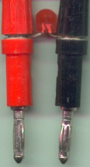
For a simple test, grab a volt meter and a visible light emitting diode (I chose a Red 650nm LED for the test because I had one with a big lens ). Connect the LED to the volt meter and expose the LED to various light sources. I get a variance of 0 mV to 1150 mV (dark to light) per LED.
Test Measurements
- Reading light, measured from the page of a book
- 50 mV
- Completely overcast sky (09:30 Local) through a triple-pane window
- 120 mV
- 50 W desk lamp
- 350 mV
- 100 W desk lamp
- 650 mV
- 150 W desk lamp
- 850 mV
- Completely clear sky, Direct (15:00 Local)
- 1150 mV
- Completely clear sky, Diffuse (15:20 Local)
- 450 mV
- Dark hallway
- 5 mV
Homebrew Projects - Components
- Details
- Category: Shack Talk
- Published on Tuesday, 28 August 2012 11:00
- Written by David L Norris, KG9AE
Many seem to think that the "Maker" phenomena is a new trend but it's really just a resurgence of how things were before mass production moved out of the US. Most of the time since radio and electricity went mainstream in the late 19th century designing and building your own equipment was the attraction. Back then it was necessary because there was no store which sold such equipment. These days you can go buy anything you'd ever need. When I was a kid in the 1980s pretty much everyone interested in Ham Radio or electronics had built a Heath Kit or Conar or some other piece of gear and almost everyone had built their own antennas. Building something of your own design is a very valuable learning experience and I strongly encourage everyone, ham or not, to build something of their own.
Sometimes building kits was to learn but often it was out of necessity. Kits are often quite inexpensive compared to the prebuilt options and if you are careful and patient and follow the directions they are normally easy to build. Mind you, complex kits may be tedious but good kits will hold your hand through the entire process. Easy to follow and inexpensive kits still exist and have amazing capabilities compared to old school kits. You can find anything from simple meters up to full digital DSP HF-VHF Transceivers comparable to, or better than, any commercial factory-built rig.
The very first piece of electronic gear of any kind that I built was a Heath Kit HM-2102 2 Meter 25W/250W Wattmeter in the late 1980s. It was new in the box and had been sitting around unbuilt for some years. So my uncle gave it to me to try and get me interested in Ham Radio. Well, I was hooked. I immediately started studying for my novice class license. Afterall, I needed a license and a radio now that I had this awesome meter!
Recycle and Share
You can begin your journey into electronics with a kit but you may find yourself needing to provide your own chassis and other hardware to complete the kit. Many kits only provide the basic electrical and electronic components and leave cabinetry and other details to you. This is really the most fun part of it all. Sure, you can go out and buy all the parts you need new from a nice hardware store. But that takes money and I'd bet most of you throw away all kinds of stuff all the time that would be hugely valuable in a homebrew project.
Don't feel like you need to do these things alone. In fact, I suggest you completely avoid doing these things alone. Maybe you feel like it would be a worthy challenge to tackle a project alone. However it is valuable to know how other people would design such a system before diving in head first. If you are lucky you will be able to locate at least one group of people in your local area that is interested in building things, as well. Here are two valuable resources to find like-minded folks in your area:
And always remember the hackerspace motto: Be Excellent to Each Other!
Parts to Scavenge
Regardless whether you are building your own design, building a kit or just providing your own custom chassis for a kit you will need a few things before you begin. You will need tools, some hardware supplies and some electronic components.
- Sheet Metal chassis covers, brackets, shields, etc
- Screws & Nuts (Machine, Sheet Metal, not wood)
- Washers (Metal, Teflon, etc)
- Gears, pulleys, clutches, etc
- Rubber Gaskets, O-Rings, Seals, belts, etc
- Rubber Feet, spacers, shock absorbers, etc
- Brakes (felt, paper, etc) - adds friction to make a knobs more precise\
- Wire, wiring harnesses
- Connectors, plugs, jacks, etc
- Meter movements
- LEDs, lamps, etc that are easy to remove
- Potentiometers, High Power resistors, rotary encoders and other knob-like bits
- Knobs! Plastic knobs to turn potentiometers, inductors, capacitors.
- Heatsinks, Radiators, Heatpipes (chunks of aluminum & copper with fins that conduct heat)
- Electrolytic Capacitors
- Transformers & Power Supplies
- Inductors, magentic coils, anything with enameled copper wire is invaluable.
- LCD Computer/TV Monitors (good bartering material with a TV shop, they usually cost $4-10 to fix if the screen itself is intact. High resell value and low cost to repair.)
Parts to Buy
If you have other scavengers nearby ask them before buying new. Like me, they may have significant stores of NOS (new-old-stock) items they have scavenged from TV/Radio shops, fleamarkets, hoarders, etc. They may be willing to barter with you; I know I will. I have been known to give away parts that are interesting but not particularly valuable. For instance, I have a box of 8088 CPUs which are utterly worthless to sell but they are a brilliant CPU to learn how CPUs work. If nothing else its a good chance to see what types of things others scavenge to give you ideas on how to go about doing so. And, hopefully, they can give you storage ideas to keep the space needed to a minimum. The goal is to have useful parts on hand without spending much money; not to be buried in parts no one will ever use.
- Microcontroller, CPU, RAM, ROM or any other IC Chip (Frys!)
- Resistors (Newark, Digikey) - Buy 100 of each standard value/precision and you're set for years. In bulk you're looking at $30 total for every possible standard resistor. At Radio Shack you're looking at $20 for a pack of 50 with 43 values you'll never use.
- Capacitors (Newark, Digikey) - NOS is best. If you must buy new avoid Korean high-density electrolytics. There is a near 100% chance of failure on high density electrolytics unless you know precisely what you are doing.
- Inductors (Newark, Digikey, specialty shops) - Learn to make your own! Its trivial and cheap. (Enameled copper wire you scavenged above)
- Vacuum Tubes (Buy NOS from scavengers if possible, Russian-made if not.)
- Transistors (Newark, Digikey, Frys)
- Proto-Circuit boards (Frys)
Standard Electronics Components
This is a list of basic electronics components that I keep on hand at all times for experimenting and building simple circuits. I also have a vast number of other devices on hand but I don't replenish those until I need more.
Resistors
Resistors come in standard values called "preferred numbers" and values are based on a geometrical progression of tolerance. The numbers used in electronics are defined in the IEC60063 E Series and come in divisions of 6, 12, 24, 48, 96, 192. Resistors with a 5% tolerance have values spaced 5% apart. 10% and 20% resistors are fairly unheard of these days but were very common in the first half of the 20th century. So you are likely to find them in salvaged items or older gear. ¼W carbon resistors are sufficient for most circuits. Sometimes you'll need a value not listed in my table and for that you can combine several smaller values at least until you can buy the exact value you need. For example, if you need a 150kΩ then a 100kΩ + 47kΩ is only 2% off the marked value. With a good meter in that situation you can grade the resistors you have on hand and with luck find some closer to your desired value.
Here are the values I keep on hand in bulk quantities. This entire set should cost under $25 to assemble from Digikey or Newark.
| 100Ω | 1kΩ | 10kΩ | 100kΩ |
| 150Ω | 1.5kΩ | 15kΩ | 150kΩ |
| 220Ω | 2.2kΩ | 22kΩ | 220kΩ |
| 330Ω | 3.3kΩ | 33kΩ | 330kΩ |
| 470Ω | 4.7kΩ | 47kΩ | 470kΩ |
| 680Ω | 6.8kΩ | 68kΩ | 680kΩ |
Capacitors
As with resistors, capacitors come in IEC60063 E series numbers rated at various voltages, temperatures, polarizations and made of a vast array of materials. Your best bet to start with is to grab an assorted parts kit. Honestly, you will never need all of these values below. Most circuits only use 4 of the E series numbers: 1, 2.2, 4.7 and 6.8 and again the reason for this is tolerance. E6 is 20% tolerance and electrolytics in particular have a typical tolerance of 40%. (What? 40%! Yep. Your 10µF may be 7-15µF.) Which exact values you'll need are entirely dependent of the types of devices you build. When in doubt, remember you can (almost) always combine smaller values effectively. Tolerances on capacitors are pretty loose unless you're dealing directly with RF and usually you can adjust the other nearby components a little to make up for not having an exact value. These tables may also help you select the correct type of capacitor for the function it will be performing.
You probably only need a fraction of these values. My rule of thumb is that if I need a value then I buy in bulk. I like to keep the shipping under 10% of the order price. For example, if I need to buy ten 470µF I'll go ahead and buy 50 of them to hit the price break. 10 might cost $7 where 50 are $18. In the US, you can go with USPS First Class mail (padded envelope) on the shipping for around $1.80 and still get it in 2 days.
| 1pF | 10pF | 100pF | 1000pF | 0.01µF | 0.1µF | 1.0µF | 10µF | 100µF | 1000µF |
| 1.5pF | 15pF | 150pF | 1500pF | 0.015µF | 0.15µF | 1.5µF | 15µF | 150µF | 1500µF |
| 2.2pF | 22pF | 220pF | 2200pF | 0.022µF | 0.22µF | 2.2µF | 22µF | 220µF | 2200µF |
| 3.3pF | 33pF | 330pF | 3300pF | 0.033µF | 0.33µF | 3.3µF | 33µF | 330µF | 3300µF |
| 4.7pF | 47pF | 470pF | 4700pF | 0.047µF | 0.47µF | 4.7µF | 47µF | 470µF | 4700µF |
| 6.8pF | 68pF | 680pF | 6800pF | 0.068µF | 0.68µF | 6.8µF | 68µF | 680µF | 6800µF |
| Ceramic | Electrolytic | Tantalum | Mylar-Polyester | Mylar-Metal-Film |
|---|---|---|---|---|
| 16V | 10V | 10V | 50V | 250V |
| 25V | 16V | 16V | 100V | 400V |
| 50V | 25V | 20V | 200V | 630V |
| 100V | 35V | 25V | 400V | |
| 600V | 50V | 35V | ||
| 1000V | 63V | 50V | ||
| 100V | ||||
| 160V | ||||
| 250V | ||||
| 350V | ||||
| 450V |
|
Transistors
There is such an awe inspiring variety of transistors available you could spend forever looking through catalogs. However, for most mundane purposes a few will suffice. You will need to seek out some specialty parts for high power RF amps and odd devices. But for day to day circuits I think this table will serve you well. Most transistor applications are going to use NPN or their equivalent. Sometimes you'll need a complimentary pair; for example, to drive a transformer such as an IF inter-stage amp you should be using complimentary pairs here. These are usually low power situations. The faster the device needs to switch the more likely you are to need more exotic devices like JFETs and MOSFETs.
| Part # | Case | Description |
| 2N3055 | TO-3 | NPN Power, 115W: Audio, Power |
| TIP47,48,49,50 | TO-220 | NPN Switching, 40W: Power Control |
| 2N3904 | TO-92 | NPN Preamp, 625mW: Audio, RF, Power, Compliments 2N2906 |
| 2N3906 | TO-92 | PNP Preamp, 625mW: Audio, RF, Power, Compliments 2N3904 |
| MPF102 | TO-92 | N-Channel JFET RF Amp, 350mW: VHF Preamplifier, IF Interstage, Switching |
| IRF510 | TO-220 | MOSFET, HEXFET, 50W: High Speed Switch |
Diodes
I'm not even going to bother listing every single part because it doesn't matter much and its like listing the names of all the stars in the sky. Buy some rectifiers (e.g. 6A, 50V), buy some switching diodes (e.g. 1N914) and I will list the Zeners I keep on hand. Zeners are used for voltage regulation and shunting (shunting: voltage gets too high and you shutdown the circuit; keeps things from exploding and/or catching fire.)
| Part # | Breakdown Volts | Max Current |
| 1N5220B | 3.3V | 200mA |
| 1N5231B | 5.1V | 20mA |
| 1N5240B | 10V | 20mA |
| 1N5242B | 12V | 20mA |
| 1N5245B | 15V | 8.5mA |
Integrated Circuits
This is just a very short list of useful ICs to have on hand. I have a few hundred times more than this but these are a good start.
| Part# | Case | Description |
| LM7805, LM7808, LM7812, LM7815 | TO-220 | 3 pin 5V, 8V, 12V, 15V regulators in a tab mount transistor case. 8V is handy because PLL circuits in radios commonly use them to power the VCO and this is a very common device to fail. |
| TL062CP | 8-PDIP | 8 Pin Operational Amplifier with 1MHz bandwidth 3.5V/µS Makes a decent Audio or IF pre-amplifier or comparator. |
| 4N36 | 6-DIP | 6 Pin Optocoupler with Transistor Output 5300V Isolation. This allows you to electrically-optically isolate the output of one analog device with the input of another analog device. Can be used for digital as well. |
| MAX232 | 16-DIP | 16 Pin RS-232 Line Transceiver. TTL/CMOS IC chips tend to be 5V unbalanced (reference to ground) with no flow control. RS-232 computer serial ports are 12V balanced (referenced to -12V) with various forms of flow control. This chip converts both ways between the two line formats. Most radios need these to talk to a PC. |
| NE555, NE556, NE558 | 8, 14, 16-DIP | 8, 14, 16 Pin Single, Dual, or Quad Timer. Marvelously wonderful and simple timing chip. You can build oscillators and whatnot with these. |
| NE567 | 8-DIP |
8 Pin Phase Locked Loop Tone Decoder. |
| 7400 series | DIP | TTL ICs that perform all sorts of logic and digital switching functions. I keep handy 7408, 7474, 7420, 7475, 7402, 7430, 7490, 7404, 7432, 74107, 7405, 7406, 7447, 7446, 74192, 74161 and the list goes on for hours. They are cheap and readily found as salvage. I find huge bags of them at fleamarkets all the time. I have dozens of other kinds, as well. If you have one you can't find I might be able to help. |
| 4000 series | DIP |
CMOS ICs that perform various digital logic and analog switching functions. |
Just as an example, this inventory from a single storage box of IC chips I have on hand:
| Prefix | Component | Quantity | Notes |
| LM | 555 | 41 | Single Timer |
| NE | 555 | 3 | Single Timer |
| LM | 733 | 3 | Differential Amplifier |
| Radio Shack | 7555 | 5 | 16-pin 555 timer |
| C | 11464 | 1 | (unknown) |
| SL | 63356 | 1 | (unknown) |
| BCFD | 1073BC | 7 | "GTE LABS" Like MC477 Dual 4-in AND gate |
| 2653N | 3 | (unknown) | |
| UA | 3302PC | 1 | (unknown) |
| SCC | 4016AE | 11 | CMOS QUAD BILATERAL SWITCH |
| CD | 4016BE | 19 | CMOS QUAD BILATERAL SWITCH |
| MC1 | 4016CP | 64 | CMOS QUAD BILATERAL SWITCH |
| CD | 4017BE | 28 | CMOS COUNTER/DIVIDERS |
| CM | 4024AF | 67 | 7-Stage Ripple Carry Binary Counter |
| CD | 4043BE | 93 | CMOS QUAD 3-STATE R/S LATCHES |
| MC | 4044P | 1 | Phase Frequency Detector |
| CD | 4051BD | 1 | Single 8 channel Analog Multiplexer/Demultiplexer |
| CD | 4051BE | 50 | Single 8 channel Analog Multiplexer/Demultiplexer |
| CD | 4052BE | 31 | Dual 4-Channel Analog Multiplexer/Demultiplexer |
| CD | 4066BE | 30 | CMOS QUAD BILATERAL SWITCH |
| CD | 4066BEX | 36 | CMOS QUAD BILATERAL SWITCH |
| MC1 | 4515AL | 2 | 4-Bit Transparent Latch/4-to-16 Line Decoder |
| MC1 | 4515CL | 2 | 4-Bit Transparent Latch/4-to-16 Line Decoder |
| MC1 | 4584B | 4 | Hex Schmitt Trigger |
| MCM | 6810LD | 5 | 128 Bytes x 8-bit RAM |
| SN | 74154J/N | 21 | 4-to-16 Line Decoder |
| SN | 7430N | 18 | 8-INPUT POSITIVE-NAND GATES |
| SN | 7442AN | 9 | 4-LINE BCD TO 10-LINE DECIMAL DECODERS |
| SN | 7474N | 10 | DUAL D-TYPE POSITIVE-EDGE-TRIGGERED FLIP-FLOPS WITH PRESET AND CLEAR |
| 74LS00N | 2 | "Controller for Timex 1000" parts bag | |
| 74LS30N | 2 | "Controller for Timex 1000" parts bag | |
| 74LS32N | 2 | "Controller for Timex 1000" parts bag | |
| Intel | P8048 | 3 | Microcontroller (Intel MCS48 series) |
| Intel | P8080A-2 | 2 | Microprocessor |
| Intel | P8255A | 16 | CMOS Programmable Peripheral Interface |
| Misc. | P82C55A | 4 | CMOS Programmable Peripheral Interface |
| Mostek | Z80A | 1 | Microprocessor |
| SGS | Z80A | 2 | Microprocessor |
| Zilog | Z80A | 4 | Microprocessor |
My list is not exhaustive. I could type until the end of time and not cover half the things you might need. I am utterly amazed all the time at the vast variety of things I've come across over the years. Most people look at a device and see only the thin veil of the outside. Me, I see through it for what it is: A big pile of parts that is eventually going to be obsolete.
Ham Spot Presents: RFID Door Lock
- Details
- Category: Ham Spot Presents
- Published on Monday, 11 June 2012 16:48
- Written by David L Norris, KG9AE
Ham Spot Bits: Rigol DS1052E & LabVIEW
- Details
- Category: Ham Spot Bits
- Published on Tuesday, 05 June 2012 16:45
- Written by David L Norris, KG9AE
Ham Spot Bits: Unboxing Day 4
- Details
- Category: Ham Spot Bits
- Published on Tuesday, 05 June 2012 16:42
- Written by David L Norris, KG9AE
Ham Spot Bits: Arduino LCD Signal Meter
- Details
- Category: Ham Spot Bits
- Published on Sunday, 03 June 2012 16:40
- Written by David L Norris, KG9AE
Ham Spot Bits: RF Madness
- Details
- Category: Ham Spot Bits
- Published on Thursday, 31 May 2012 16:38
- Written by David L Norris, KG9AE
Ham Spot Bits: What Good is a Scope Anyway
- Details
- Category: Ham Spot Bits
- Published on Tuesday, 01 May 2012 16:37
- Written by David L Norris, KG9AE
Ham Spot Bits: Fun 'n Games
- Details
- Category: Ham Spot Bits
- Published on Thursday, 19 April 2012 16:33
- Written by David L Norris, KG9AE
Ham Spot Bits: Unboxing Day Too
- Details
- Category: Ham Spot Bits
- Published on Wednesday, 18 April 2012 16:32
- Written by David L Norris, KG9AE
Ham Spot Bits: Unboxing Day
- Details
- Category: Ham Spot Bits
- Published on Wednesday, 18 April 2012 16:31
- Written by David L Norris, KG9AE
Ham Spot Bits: Nano TVout
- Details
- Category: Ham Spot Bits
- Published on Wednesday, 18 April 2012 16:16
- Written by David L Norris, KG9AE
Ham Spot Bits: Nano Spectrum Analyzer
- Details
- Category: Ham Spot Bits
- Published on Wednesday, 18 April 2012 02:02
- Written by David L Norris, KG9AE
Ham Spot Bits: Nano AVR Programmer
- Details
- Category: Ham Spot Bits
- Published on Tuesday, 17 April 2012 05:18
- Written by David L Norris, KG9AE
I use an Arduino Nano to burn the Arduino bootloader to a blank ATMEGA328P chip.
Ham Spot Bits: Touchscreen HF Operation
- Details
- Category: Ham Spot Bits
- Published on Sunday, 08 April 2012 02:02
- Written by David L Norris, KG9AE
Just a couple of short videos I made showing the use of a touchscreen with Ham Radio Deluxe and Digital Master with an Icom IC-746PRO.
Ham Spot Bits: Touch Dimmer Repair
- Details
- Category: Ham Spot Bits
- Published on Thursday, 23 February 2012 23:03
- Written by David L Norris, KG9AE
In this video I repair a touch dimmer control. This device is inserted between a lamp and the wall receptacle.
A touch sensor is created by extending one plate of a very low value capacitor to a larger metal surface. The capacitor is alternately charged and discharged several hundred times per second. When a large conductive object, such as a person, touches the plate the discharge rate of the capacitor is slowed. The touch sensor circuit measures the discharge rate comparing it to a stable timer. If the discharge rate changes for more than a few dozen milliseconds the sensor triggers a mode change in the dimmer.
In principal, this works similar to the Arduino circuit I built recently. The main difference is that the Arduino version of this circuit was done mostly in software. The only external components required for the Arduino were the 1nF capacitor and the metal touch plate.
Ham Spot Bits: Touchy Feely
- Details
- Category: Ham Spot Bits
- Published on Saturday, 18 February 2012 18:51
- Written by David L Norris, KG9AE
Arduino Nano capacitive touch lamp control proof of concept. I salvage a lamp from Goodwill and retrofit it with LEDs instead of Halogens. Implements a debounce algorithm to help prevent false triggers. This will later be transformed into an interactive lamp with various lighting modes.
I put together a custom sketch based on some other examples in the documentation and wiki to perform the desired tasks.
Source Code for TouchLamp.ino
/* Debounce Each time the input pin goes from LOW to HIGH (e.g. because of a push-button press), the output pin is toggled from LOW to HIGH or HIGH to LOW. There's a minimum delay between toggles to debounce the circuit (i.e. to ignore noise). The circuit: * LED attached from pin 13 to ground * pushbutton attached from pin 2 to +5V * 10K resistor attached from pin 2 to ground * Note: On most Arduino boards, there is already an LED on the board connected to pin 13, so you don't need any extra components for this example. created 21 November 2006 by David A. Mellis modified 30 Aug 2011 by Limor Fried This example code is in the public domain. http://www.arduino.cc/en/Tutorial/Debounce */ // constants won't change. They're used here to // set pin numbers: const int buttonPin = 2; // the number of the pushbutton pin const int ledPin = 13; // the number of the LED pin // sensor key #define TOUCHPORT 1<<PINB0 // Variables will change: int ledState = HIGH; // the current state of the output pin int buttonState; // the current reading from the input pin int lastButtonState = LOW; // the previous reading from the input pin // the following variables are long's because the time, measured in miliseconds, // will quickly become a bigger number than can be stored in an int. long lastDebounceTime = 0; // the last time the output pin was toggled long debounceDelay = 100; // the debounce time; increase if the output flickers // calbration occurs at startup only int calibrate = 0; int capval = 0; void setup() { Serial.begin(9600); pinMode(buttonPin, INPUT); pinMode(ledPin, OUTPUT); delay(100); // let the circuit settle a bit calibrate = getcap(TOUCHPORT) + 1; } void loop() { // read the state of the switch into a local variable: int reading = readplate(); // check to see if you just pressed the button // (i.e. the input went from LOW to HIGH), and you've waited // long enough since the last press to ignore any noise: // If the switch changed, due to noise or pressing: if (reading != lastButtonState) { // reset the debouncing timer lastDebounceTime = millis(); } if ((millis() - lastDebounceTime) > debounceDelay) { // whatever the reading is at, it's been there for longer // than the debounce delay, so take it as the actual current state: buttonState = reading; } // set the LED using the state of the button: digitalWrite(ledPin, buttonState); // save the reading. Next time through the loop, // it'll be the lastButtonState: lastButtonState = reading; } boolean readplate() { capval = getcap(TOUCHPORT); if( capval > calibrate ){ Serial.print(capval, DEC); Serial.print(" > "); Serial.print(calibrate, DEC); Serial.println( " HIGH" ); return HIGH; } else { Serial.print(capval, DEC); Serial.println( "LOW" ); return LOW; } } // returns capacity on one input pin // pin must be the bitmask for the pin e.g. (1<<PB0) char getcap(char pin) { char i = 0; DDRB &= ~pin; // input PORTB |= pin; // pullup on for(i = 0; i < 16; i++) if( (PINB & pin) ) break; PORTB &= ~pin; // low level DDRB |= pin; // discharge return i; }
Ham Spot Bits: Arduino Nano Onboard
- Details
- Category: Ham Spot Bits
- Published on Saturday, 18 February 2012 18:37
- Written by David L Norris, KG9AE
In this segment I unbox my newly arrived Arduino Nano 3.0 from Gravitech.us and sort out a wire kit I purchased.
After some experimenting with the Arduino Uno I decided it would be useful to have a breadboard mounted microcontroller. I ran across several Arduino variations that mounted directly to a standard breadboard. After some feature comparison I chose the Nano because its basically identical in features to the Uno I already have.
Bonus Tips: If you watch carefully you'll notice I am constantly putting my tools back where they belong as I work. A lesson learned with time. I have found that if I constantly put my tools back where they belong I don't have to think about where it is when I need it. I can blindly grab the tool and use it without disrupting my workflow. Same goes for having too much trash and spare parts in your work area. Keep it clean and its not distracting you from your tasks.
Ham Spot Presents #002: Potential Capacitors
- Details
- Category: Ham Spot Presents
- Published on Friday, 17 February 2012 12:00
- Written by David L Norris, KG9AE
In this video we examine a variety of specialty capacitors as well as some common components. I smash open a high voltage capacitor to see what's inside. I show you a vintage resistor-capacitor tester. Another look at how I store all of these devices. And at the end is a tidbit for Ham Radio operators who have need for high power medium-wave/short-wave antenna matching.
There are an endless variety of capacitors available on the market as well as many you can salvage from old equipment.
Capacitor Sources
Be careful about where you purchase capacitors, as well. There are plenty of counterfeit devices on the market today, unfortunately. Newark.com and Digikey.com are excellent, reliable and inexpensive sources for components.
I usually buy new electrolytics just to be safe. Electrolytics deteriorate with age. Some are very poor quality to begin with.
However many types of capacitors are ripe for salvage. Air dielectric, high voltage, high capacity and many specialty capacitors are worth the trouble of salvaging. Some types of capacitor simply are no longer manufactured and suitable replacements do not exist. In those cases you are forced to purchase work-alike circuits from antique vendors such as Antique Electronics Supply that are often disguised to look like the original part. Not always ideal especially if you can find a working original replacement part.
Air dielectric capacitors can be purchased directly from MFJ Enterprises, as well. These will be the type more suitable to building radios and antenna matching circuits. Other commercial sources for these components have largely gone extinct.
Common Capacitors
Your best bet is to grab an assorted parts bag from someone or somewhere. Honestly, you don't need all of these values. Which values you'll need are entirely dependent of the types of devices you build. When in doubt, remember you can (almost) always combine smaller values effectively. Tolerances on capacitors are pretty loose unless you're dealing directly with RF and usually you can adjust the other nearby components a little to make up for not having an exact value. These tables may also help you select the correct type of capacitor for the function it will be performing.
| 1pF | 10pF | 100pF | 1000pF | 0.01µF | 0.1µF | 1.0µF | 10µF | 100µF | 1000µF |
| 1.5pF | 15pF | 150pF | 1500pF | 0.015µF | 0.15µF | 1.5µF | 15µF | 150µF | 1500µF |
| 2.2pF | 22pF | 220pF | 2200pF | 0.022µF | 0.22µF | 2.2µF | 22µF | 220µF | 2200µF |
| 3.3pF | 33pF | 330pF | 3300pF | 0.033µF | 0.33µF | 3.3µF | 33µF | 330µF | 3300µF |
| 4.7pF | 47pF | 470pF | 4700pF | 0.047µF | 0.47µF | 4.7µF | 47µF | 470µF | 4700µF |
| 6.8pF | 68pF | 680pF | 6800pF | 0.068µF | 0.68µF | 6.8µF | 68µF | 680µF | 6800µF |
| Ceramic | Electrolytic | Tantalum | Mylar-Polyester | Mylar-Metal-Film |
|---|---|---|---|---|
| 16V | 10V | 10V | 50V | 250V |
| 25V | 16V | 16V | 100V | 400V |
| 50V | 25V | 20V | 200V | 630V |
| 100V | 35V | 25V | 400V | |
| 600V | 50V | 35V | ||
| 1000V | 63V | 50V | ||
| 100V | ||||
| 160V | ||||
| 250V | ||||
| 350V | ||||
| 450V |
|
Ham Spot Presents #001: Resistors of a Different Color
- Details
- Category: Ham Spot Presents
- Published on Thursday, 09 February 2012 04:56
- Written by David L Norris, KG9AE
In this video I present a variety of common types of resistors used in the last 50 years. I do not cover current technologies such as surface-mount components as these will be the most familiar to new builders.
Most circuits only need simple low wattage fixed carbon resistors. However there are plenty of cases where you might need something more substantial. For example, a conventional DC power supply will need very low resistance high wattage ballast resistors, probably wire wound, to balance the current flowing through each pass transistor. For testing a transmitter you will need very high power carbon resistors; more common high power wire wound resistors are inductive at radio frequencies.
You may want a variable resistance in many circuits. This could be a simple carbon pot to adjust a signal level or high power wire-wound for adjusting brightness on a incandescent bulb. This is where potentiometers rule the world. But it would be a mistake to think that potentiometers are the only option for varying resistance. Many devices vary resistance based on environmental factors such as ambient light, temperature or pressure.
Carbon film resistors come in standard values. These values are based on a geometric progression of the tolerance. All resistors with a 5% tolerance have values spaced 5% apart. 10% and 20% resistors are fairly unheard of these days but were very common in the first half of the 20th century. So you are likely to find them in salvaged items or older gear. Here is a table of standard values that I suggest you keep on hand. ¼W carbon resistors are sufficient for most circuits. Sometimes you'll need a value not listed in my table and for that you can combine several smaller values at least until you can buy the exact value you need. For example, if you need a 150kΩ then a 100kΩ + 47kΩ is only 2% off.
| 100Ω | 1kΩ | 10kΩ | 100kΩ |
| 150Ω | 1.5kΩ | 15kΩ | |
| 220Ω | 2.2kΩ | 22kΩ | |
| 330Ω | 3.3kΩ | 33kΩ | 39kΩ |
| 4.7kΩ | 47kΩ | 470kΩ | |
| 5.1kΩ | 51kΩ | 510kΩ | |
| 680Ω | 6.8kΩ | 68kΩ |